|
SCR-584 Mobile Short Range Auto Tracking Radar Set - A Mobile Short Range Auto Tracking Radar set built by Westinghouse, General Electric and Chrysler during World War II. Initially developed by the MIT Radiation Laboratory as a gun laying radar using recently developed 2J32 magnetron tube as a microwave power source. The set operated on four frequencies between 2,700 and 2,800 MHz.
|
|
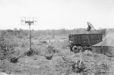 SCR-584 at Peleliu, Antenna on Left is for the RC-184 IFF Set. |
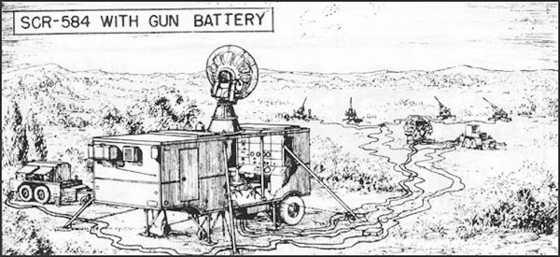 Sketch of SCR-584 Auto Tracking Radar Installation. Two units in front of the guns are for the M-9 Director. Unit on the left is the M-7 Generator. |
The SCR-584 set had a search mode with a range of 40-50 miles and could switch to automatic tracking mode when the target reached within 18 miles. When in the tracking mode target data could be fed to position a nearby anti-aircraft gun battery. The set also presented azimuth and angular height to searchlight control station for directing searchlight as well as transmitting present azimuth, angular height, and altitude to M-4, M-7, or M-9 directors for gun-laying.
The set was self-contained, built on a K-78 trailer and meant for forward area deployment. Its gross weight was 10 short tons. The overall length was 19.5 feet, width was 8 feet, height 10 feet, 4 inches. A towed trailer contained a generator power source. Thirteen men could install the set and obtain approximate data in 2 hrs. Accurate orientation and alignment took 4 additional hours.
The SCR-584 was first used in combat at Anzio in February 1944, where it played a key role in breaking up German air attacks on the confined beachhead. Employed in England against the German V1 flying bombs it achieved remarkable success.
SCR-584 Auto Tracking Radar
SCR-584 Auto Tracking Radar
| Element
|
Value
|
Notes
|
| Nomenclature |
SCR-584 |
|
| Variants |
SCR-584-A, SCR-584-B |
|
| Manufacturer |
Westinghouse (1,275)
Chrysler (1,275)
General Electric (1,275) |
|
| Type |
Auto Tracking Radar |
|
| Number Made |
3,825 |
Original contract
|
| IEEE Band |
S Band |
|
| Frequency |
4 frequencies between 2,700 and 2,800 MHz |
|
| PRF |
1707 pps |
|
| Pulse Width |
0.8 us |
|
| RF Power |
250 kW peak |
|
| Antenna Diameter |
6 feet |
Conical scan
|
| Rotation Speed |
5 rpm |
Search mode
|
Beam width to
half power points |
4 degrees |
|
| Range |
39.7 mi Search
18.2 mi Auto track |
Short Range
|
| Range Error |
25 yards |
|
| Azimuth Error |
1 mil (0.06 degree) |
|
| Elevation Accuracy |
1 mil (0.06 degree) |
|
| IFF |
RC-184 |
MK-3 IFF Set
|
| AC Power |
115 V, 60 Hz, 3 phase,
10 kVA maximum (without IFF)
Some early units used 400hz power |
M7 Generator furnished
|
| Introduced |
May 1943 |
1st Production model
|
|
 SCR-584 Operator Console.  M-7 Generator Set with all Panels Open. |
SCR-584 Radar Set Manuals:
- TM 11-1324 - Radio sets SCR-584-A and SCR-584-B technical operation manual
- TM 11-1424 - Radio sets SCR-584-A and SCR-584-B preventive maintenance manual
- TM 11-1524 - Radio sets SCR-584-A and SCR-584-B service manual
RC-184 IFF Set Manuals:
- TM 11-1332 - Technical operation manual: Radio equipment RC-184
- TM 11-1432 - Preventive maintenance manual: Radio equipment RC-184
- TM 11-1532 - Service manual: Radio equipment RC-184
See Also:
Sources:
- Thompson, Harris, Oakes & Terrett, The Signal Corps: the test (December 1941 to July 1943), Office of the Chief of Military History, Dept. of the Army, 1957 - World War, 1939-1945 - 621 pages, Pdf, pages 265-274.
- U.S. Navy - U.S. Radar Operational Characteristics of Radar Classified by Tactical Application FTP 217, page 50.
Links:
|


